Feeders Part 1: What is a Feeder?

By: Dennis Bordeaux | Feb 01, 2018
You are viewing: What Is An Electrical Feeder
In order to understand what a feeder is, it is best to start with what a feeder is not.
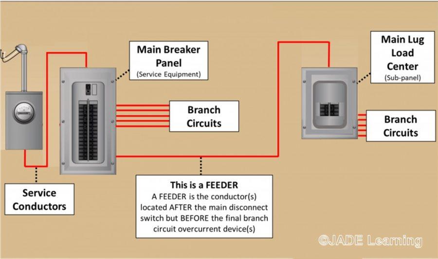
The conductors between the utility service point and the service disconnecting means are service conductors, not feeder conductors. Special service conductor rules apply because these conductors do not have short-circuit or ground-fault protection other than what is provided on the primary side of the utility transformer. Service conductors are not feeders.
Branch circuits are not feeders. A branch circuit is defined as, the circuit conductors between the final overcurrent device protecting the circuit and the outlet(s). Even the conductors for a circuit rated at 1000-amps is a branch circuit if the conductors are on the load side of the final branch circuit overcurrent device. The conductors on the load side of the final branch circuit overcurrent device are branch circuit conductors, not feeder conductors, no matter how large the circuit rating.
Read more : What Is A Buckslip
So, feeder conductors are conductors that are not service conductors and not branch circuit conductors. All circuit conductors between the load side of the service equipment and the line side of the final branch circuit overcurrent device are feeder conductors. The definition of a feeder also includes the conductors from the source of a separately derived system or other non-utility power supply source and the final branch circuit overcurrent device.
A Type SER cable between a 200-amp residential service disconnect and a subpanel is a feeder. The conductors between an 800-amp circuit breaker and a fused branch circuit disconnect supplying a single motor are also feeder conductors. So are the conductors between a standby generator and an emergency transfer switch. Although the overcurrent protection rules for these different feeders vary depending on the load(s) supplied, overcurrent protection is typically provided at the supply end of the feeder.
The conductors between the secondary side of a 480-volt/208-volt transformer and the secondary-side overcurrent device are feeder conductors as well, but are not considered to be protected by the transformer circuit primary overcurrent device.
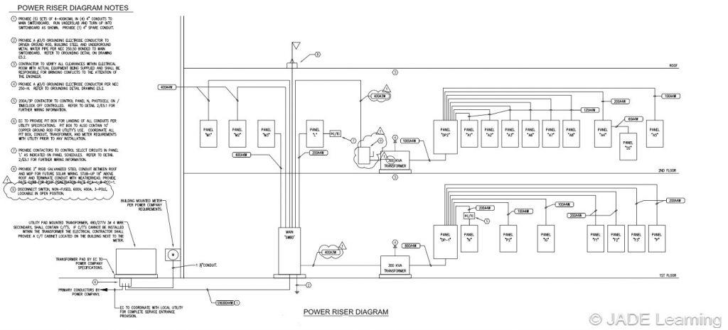
 Prior to the installation of feeder conductors, the authority having jurisdiction may require a feeder diagram. A feeder diagram should include the total calculated load on the feeder and any demand factors used in sizing the feeder conductors. The size and type of feeder conductors, as well as the rating of the feeder overcurrent protective devices, should also be included with the feeder diagram.
A typical electrical system may have many types of feeders supplying many different types of loads. Feeders supplying a combination of continuous and noncontinuous loads, motor feeders, outside feeders or feeders to separate buildings are often included on a feeder diagram. In many cases there may be feeders from more than one voltage system on the same premises. DC system feeders may also be present.

Read more : What Are Muse Chews
________________
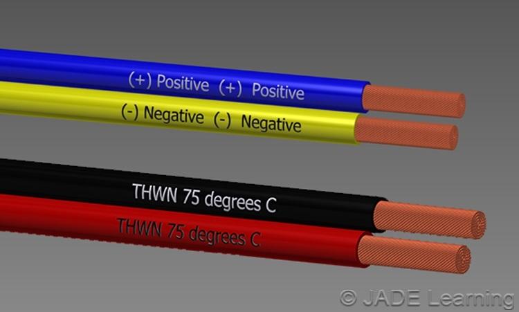
Where feeders supplied from different voltage systems are present, each ungrounded conductor must be identified by phase or line and system at all termination, connection, and splice points. Identification of ungrounded AC system conductors may be by color coding, marking tape, tagging, or other approved means. Ungrounded feeder conductors supplied by a DC system must be identified by one of the methods listed in 215.12(C)(2). The color red is permitted to be used to identify an ungrounded positive polarity conductor and the color black is permitted to identify an ungrounded negative polarity conductor.

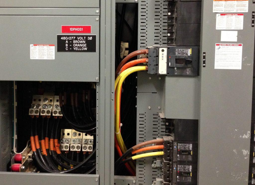
With the exception of high-leg systems and isolated power systems, the NEC does not require specific colors to identify ungrounded AC conductors. The NEC mandates the use of the color orange to identify the high-leg of a 4-wire delta-connected system where the mid-point of one phase winding is grounded (110.15). If a high-leg system is present on the same premises with a 480-volt system, the common practice of identifying 480-volt feeder conductors using the colors brown, orange, and yellow may need to be adjusted. Marking tape, tagging or other approved means of feeder identification may be required to distinguish the different feeder voltages.
Grounded feeder conductors if present, including grounded DC system conductors, must be identified in accordance with 200.6. Where grounded conductors of different voltage systems are installed in the same enclosure or raceway, each grounded conductor must be identified by system.
The feeder identification method used is required to be posted at each feeder panelboard or documented and readily available to those who will service the electrical system. Using a standard feeder identification method throughout the premises wiring system allows a qualified person to quickly identify the phase and voltage of the feeder conductors at all termination or splice points after the installation is completed.
Want to know more? Log into your JADE Learning account or register a free account and begin taking online electrical classes to satisfy you continuing education hours. Check out our catalogue of electrical license exam prep courses today.
Source: https://t-tees.com
Category: WHAT
