
QUESTION
I would like to create and display exposed rafter tails in designs. How can I do this?
You may be interested
ANSWER
Read more : What Are The 4 Phases Of Planned Maintenance
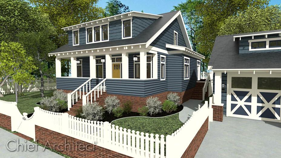
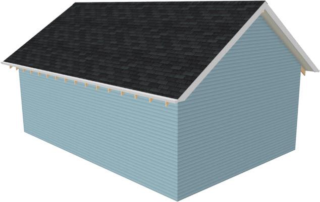
Rafter tails are rafter ends that overhang the bearing walls and are located under the eaves. They can be the full rafter depth or trimmed to the depth of the soffits and sometimes feature decorative profiles. Rafter tails can also be fully exposed, or partially enclosed by soffits.
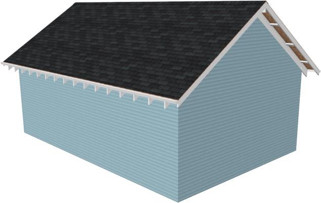
- To create fully exposed rafter tails
- To create partially exposed rafter tails
This article assumes you have already specified your Roof Framing Defaults.
To create fully exposed rafter tails
- Open the plan file in which you would like to create exposed rafter tails.
- Select Build> Roof> Build Roof and in the Build Roof dialog that displays:
- On the Roof panel, check the Build Roof Planes box.
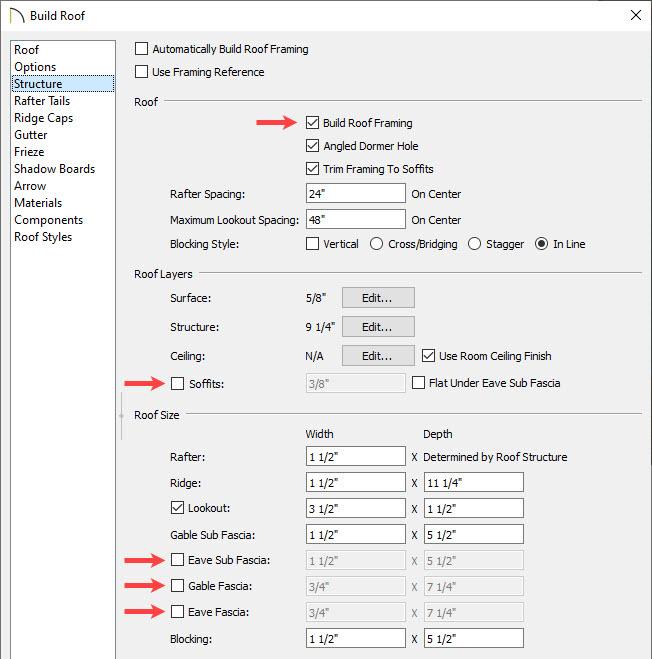
- On the Structure panel:
- Check Build Roof Framing
- Remove the check from Soffits
- Remove the check from Eave Sub Fascia
- Remove the check from Gable Fascia
- Remove the check from Eave Fascia.
- If a decorative rafter end is going to be used, select the Rafter Tails panel and click Add New to browse the library for a suitable rafter tail profile.
- If the decorative end extends past the inside surface of the subfascia, specify a desired value in the Extend column for the profile.
- Click OK to close the dialog and generate the roof.
- If a Question dialog appears, click Yes if you want to see the rafters displayed in the plan view, or click No if you don’t want to see the rafters in the plan view.
- Select 3D> Create Perspective View> Perspective Full Overview to create a 3D view of the structure.
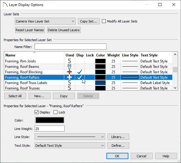
- Framing layers are not displayed in this type of camera view by default. To turn on roof rafters, select Tools> Layer Settings> Display Options and in the Layer Display Options dialog that opens:

- Verify that the correct Layer Set is selected. In this example, the Camera View Layer Set is selected, which is the default for the Perspective Full Overview tool.
- Locate the Framing, Roof Rafters layer and place a check in the Disp column.
- Click OK to confirm the change and close the dialog.
To create partially exposed rafter tails
- Open the plan file in which you would like to create exposed rafter tails.
- Select Build> Roof> Build Roof and in the Build Roof dialog:
- On the Roof panel, check the Build Roof Planes box.
- On the Structure panel:
- Check Build Roof Framing
- Remove the check from Trim Framing to Soffits
- Check Soffits
- Specify the desired Fascia and Sub Fascia Depths. For this example, the Gable Sub Fascia Depth is set to 3″, the Eave Sub Fascia Depth is set to 2″, and the Eave Fascia Depth is set to 2 1/2″.
- If a decorative rafter end is going to be used, select the Rafter Tails panel and click Add New to browse the library for a suitable rafter tail profile.
- Click OK to accept the changes and close the dialog.
- If a Question dialog appears, click Yes if you want to see the rafters displayed in the plan view, or click No if you don’t want to see the rafters in the plan view.
- Select 3D> Create Perspective View> Perspective Full Overview to create a 3D view of the structure.
- Framing layers are not displayed in this type of camera view by default. To turn on roof rafters, select Tools> Layer Settings> Display Options and in the Layer Display Options dialog that opens:
- Verify that the correct Layer Set is selected. In this example, the Camera View Layer Set is selected, which is the default for the Perspective Full Overview tool.
- Locate the Framing, Roof Rafters layer and place a check in the Disp column.
- Click OK to confirm the change and close the dialog.
Source: https://t-tees.com
Category: WHAT