DC Insulation Resistance (IR)
DC Insulation Resistance (IR) is a universally accepted diagnostic test for insulation assessment. It has been in use for more than 75 years. The IR test measures the resistance of the electrical insulation between the conductor and ground. Ideally the value of this resistance is infinite since the purpose of the insulation is to block current flow between the two electrodes. In practice this is not the case and some level of leakage current is expected, however, the resistance should have a high enough value to avoid any appreciable leakage current. A low or progressively diminishing IR value indicates that the insulation may have deteriorated.
DC resistance is the simplest form of insulation diagnostic and is calculated using the Ohm’s law: R = V / I. To achieve meaningful results, the magnitude of the applied voltage should somewhat correlate to the insulation voltage class of device under test.
You are viewing: What Is Index In Dic Macine

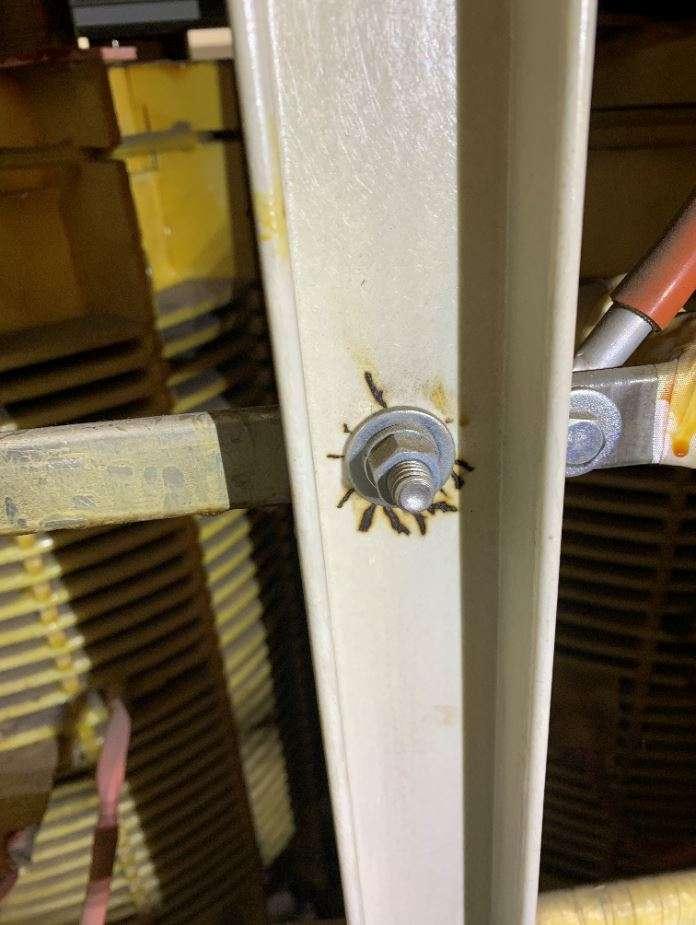
Figure 1- MV dry transformer GPO board insulation shown with electrical treeing marks
Polarization Index (PI)
Polarization Index (PI) is a variation of the IR test. It is the ratio of IR measured after voltage has been applied for some time. To standardize the practice 10 minutes has been universally accepted as the interval due to experience and correlation in rotating machine insulation material. Hence PI is (R10) to the IR measured after one minute (R1).
The characteristics of the insulation under test may be such that the current. It is not constant over the duration of the test. The purpose of measuring PI can be understood by knowing the four different current flows in the insulator which are:
1- Capacitive Current (lC)
Read more : What Water Pressure For Rv
2- Conduction Current (IG)
3- Surface leakage current (IL)
4- Absorption current (IA)
Figure 2- Equivalent circuit showing 4 currents monitored during a DC IR test[1]
Types of current flow Under applied DC
1- Capacitive current:
Insulator behave as a capacitor; when DC voltage is applied to a capacitor, a high charging current first flows and then it decays exponentially. The size of the capacitor and the internal resistance of the voltage supply, typically a few hundred kilo ohms, set the rate of current decay. The parameters associated with the charge and discharge decay are important in advance diagnostic techniques, requiring advanced equipment capable of evaluating frequency and rise time characteristics. When using simple DC insulation test devices, this capability is not present, hence the capacitive current properties are disregarded, and the initial IR is measured once the capacitive current has decayed to zero. Hence in a PI test the first IR measurement has been set at one minute to ensure that this current does not distort the IR calculation.
2- Conduction current:
This current is due to the flow of electrons between the Conductor and the ground. This is galvanic current through ground wall. Such a current can flow if the ground wall has absorbed moisture, which can happen on the older thermoplastic insulation systems. The current may also flow if there are cracks, cuts or pinholes in the ground insulation and some contamination is present to allow current to flow.
3- Surface leakage current:
This is constant DC current that flows over the surface of the insulation. It is caused by conductive contamination (oil or moisture mixed with dust, dirt, insects, chemicals etc) on the surface.
4- Absorption current:
Read more : What To Serve With Sausage Peppers And Onions
This has two components. The first component is due to the polarization of the impregnating materials because the organic molecules used in insulating material such as epoxy, tend to change orientation in the presence of a direct electric field. Since these molecules have to strain against the attractive forces of other molecules, it usually takes several minutes after application of the electric field for the molecules to become reoriented, and, thus, for the current-supplied polarizing energy to be reduced to almost zero. A second component of the absorption current is due to the gradual drift of electrons and ions through most organic materials. These electrons and ions drift until they become trapped.
Characteristics of different insulating materials
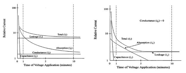
Different HV equipment and insulating systems will have distinctively different characteristics when it comes to the above 4 current contributions. Some properties of the IR and time dependency may change as the insulation system is at different temperatures, wet, contaminated or oxidized. The following figures demonstrate this statement.

Figure 3- Asphaltic Mica(Left) and Epoxy Mica(Right) insulation characteristics in Rotating Machines[1]
Figure 4- IR and PI example from three different generators [1]
There are a large variety of insulating mediums and high voltage applications in use. DC insulation testing is a simple and cost affective tool in a rudimentary assessment of the insulation. However, from above it should be clear that there is more than meets the eye; the selection of voltage, temperature, type of insulation, type of application, age and perceived condition are just among some of the factors that go into deciding on the parameters of the test as well as acceptance and assessment criteria.
Source:
[1] IEEE-STD 43-2000 Recommended Practice for Testing Insulation Resistance of Rotating Machinery 2000.
Source: https://t-tees.com
Category: WHAT
