

This is week 7 of the Google Professional IT Certification course on coursera.org.
The Google IT Support Professional Certification Program from Coursera.org is all about networking. Finally! I hope this second section really picks up in technical instruction. The first course, Technical Support Fundamentals, was really more an overview of concepts and topics one may hope to study when changing careers into the exciting world of information technology. Networking is probably the most important area where a level of expertise is needed in any IT role. Let’s watch the intro video…
You are viewing: What Modulation Type Is Used For Computer Networks Coursera
Course Introduction
The first half of this video introduces us to Victor, our host, and how he grew up with an interest in computers and then went to work in IT and went to college and now works at Google in corporate IT project management. To my surprise, he needs to know about networking to do his job.
Victor explains that when communicating, machines follow a set of rules to determine how communications are initiated, conducted, and terminated. These rules are called Protocols, which are a defined set of standards that computers must follow in order to communicate properly.
Computer networking: the name we’ve given to the full scope of how computers communicate with each other.
This course will be using the 5 layer TCP/IP model, and will reference the OSI model, which has seven layers. These protocol layers each “carry” the layers above them, and allow data to successfully travel short distances or around the world.
Now I am presented with an explanation that I will be offered an entrance survey after the first module. This survey will not affect my grade. I guess I can be truthful, then.
There is also an info page about the code of conduct in the forums and an invitation to check out the “Meet and Greet Forum,” which is a surprisingly interesting read. Lots of cheerful “good luck” talk as well as the ubiquitous career-induced self-doubt. People are seeing this course as a bridge across the void. Oh boy!
The TCP/IP Five-Layer Network Model

A true mastery of networking involves understanding everything from the cables to the devices and the protocols. One way of helping understand the protocols is the five-layer model, a homemade approximation of which you can see to the right.
Physical Layer: Represents the physical devices that interconnect computers. This includes the specifications for the actual cables and connectors, along with specifications for how signals are sent over these connections.
Data Link Layer: Responsible for defining a common way of interpreting these signals so network devices can communicate. There are many protocols used in the data link layer, but the most common is Ethernet, the standards for which also include protocol responsible for getting data to nodes on the same network.
Network Layer: Allows different networks to communicate with each other through devices known as routers. An “internetwork” is a collection of networks connected trough routers. One well known “internetwork” is the Internet. The most common protocol at this layer is known as IP (Internet Protocol). IP is the “heart of the internet” and most small networks.
Transport Layer: Sorts out which client and server programs are supposed to get that data. This means that if you have your email program open and a browser you may be sending requests to different servers, but transport protocols keeps everything going to the right part of your system. TCP (Transmission Control Protocol) is the most commonly used in the Transport Layer.
Application Layer: These are the protocols used to utilize data for specific programs on your computer. The Transport layer gets it to the application and the application layer opens it up and does stuff with it…I think… this video kind of trails off here without the same level of explanation now as given during the previous 4 layers.
There is also a reading assignment about the OSI model. The main difference is that the OSI model is a 7-layer model, where the Application Layer has three layers. I have read this all before (maybe on a slow day during my internship when I was trying to learn how subnetting works) so I am kind of skimming it.
I just turned on the FreeCodeCamp Radio channel on YouTube for some good background music.
Then there’s a short video where a guy says that the course is good and that it teaches networking in a way that will be really useful for someone who is going to work in IT. Far be it from me to tell Google how to run their business, but we’ve already signed up, guys, why the commercial?
Cables
Okay, the really fun stuff!
Cables connect different devices to each other, allowing data to be transmitted over them.
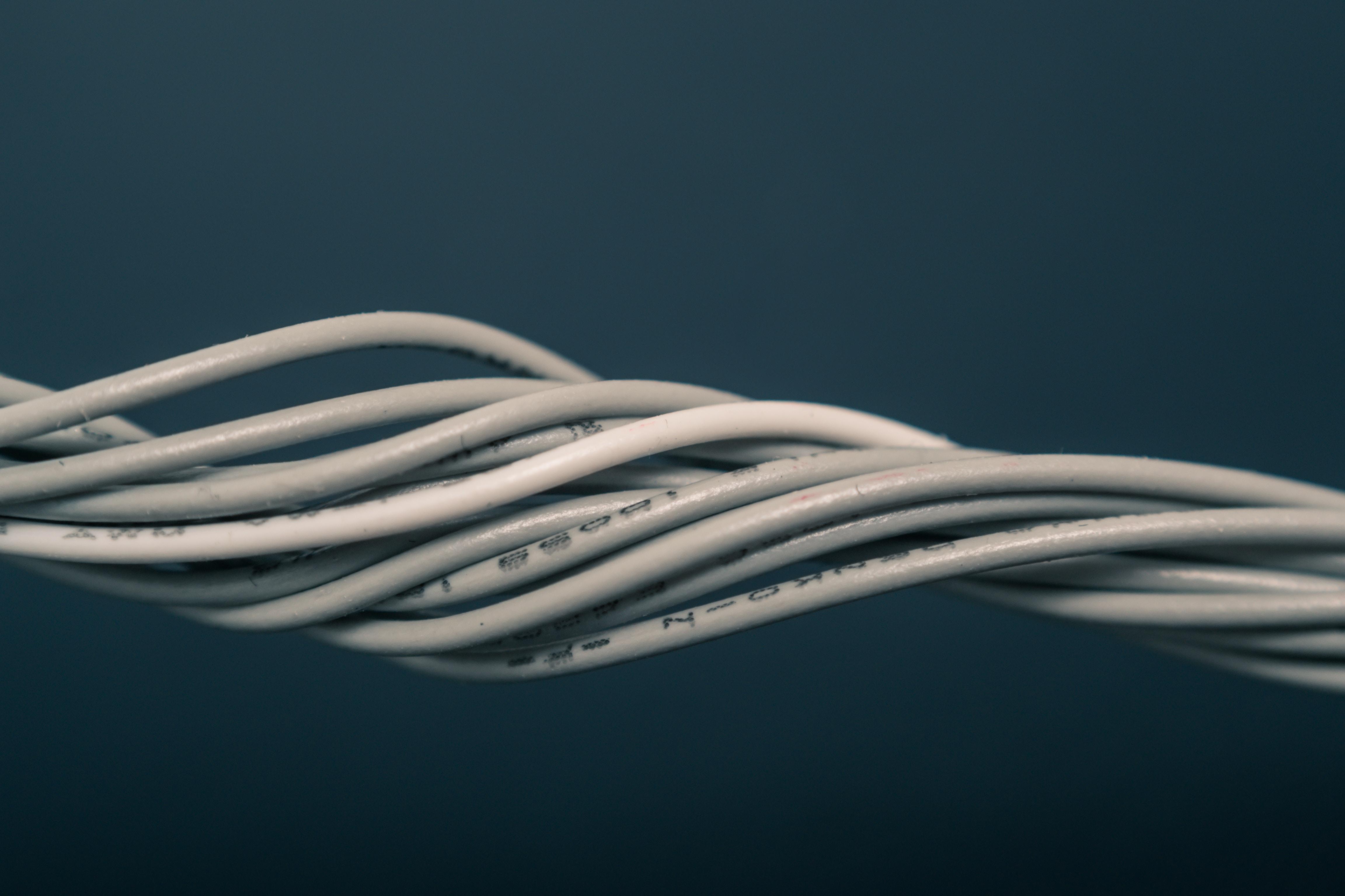
Today there are two basic types of network cable, copper and fiber. Copper cables are more common, and are made of pairs of copper wires, which carry electrical pulses encoded as ones and zeroes. The most common ones today are twisted-pair cables, either Cat5, Cat5e, or Cat6. The biggest differences in these cables are their speeds and how, internally, the wires are arranged to reduce crosstalk, which is when a signal from one wire is detected on another wire. Crosstalk creates errors which must be negotiated by higher-level protocols. Cat6 cables have the most reliable transmission and higher speeds, but because of the internal arrangement they have shorter maximum run lengths when used at higher speeds.
Read more : What Sign Is Kevin Gates
Fiber cables are made of small tubes of glass which carry pulses of light that are encoded as ones and zeroes. They are often used in environments where there is a lot of electromagnetic interference, as they are non-metallic. Fiber are much faster but also much more delicate and expensive.
Hubs and Switches
A Point-to-Point network connection exists when there is only one device at each end of the connection. There are network devices that allow many devices to communicate with each other through the device, eliminating the need to have every device physically connected with every other device.
The most simple of these devices is a hub, which is a physical layer device that allows for connections from many computers at once. Each device connected to the hub will communicate with all the others. It is up to each device to determine if incoming data is intended for it or another device. This creates a lot of noise on the network, and creates what is known as a collision domain: a network segment where only one device can communicate at a time. If multiple systems try sending data at the same time, the electrical pulses sent across the cable can interfere with each other. This means each device has to wait for a “quiet” moment to send data, resulting in slow networks. That is why hubs are not popular anymore.
Network Switches are similar to hubs, but while a hub is a Physical (Layer 1) device, a switch is Data Link (Layer 2) device. That means a switch can actually read the Ethernet protocol data and determine which device the data is intended for and then only send it to that system. This reduces or eliminates the creation of collision domains on a network.
Routers
Hubs and switches are the primary devices used to connect computers on a single network, usually referred to as a LAN, or Local Area Network. If you want to send data to a different network, you need a router.A router is a device that knows how to forward data between independent networks. Routers, as you may have guessed (I didn’t) is a Layer 3 device, operating on the Network layer, inspecting IP data to determine where to send data.
The most common router is the kind found in your home or office, which is a fairly simple device, intended only to handle traffic from inside your home or office’s small network and send it to your ISP, where it is handled by a much more sophisticated router, called a core router, which is part of the “backbone” of the internet. Core routers usually have many connections to many other routers, sharing data using a protocol known as BGP (Border Gateway Protocol) which lets them learn about the most optimal paths to forward traffic. These routers are global guides that get your traffic to the right place.
Servers and Clients
Servers send data to a device (or program) that is requesting it, known as a client. Often, the same node (machine, program, something on a network) can act like a server or a client. A machine you may call “the email server” is technically a client of a DNS server, but its primary job is that of an email server.
I am finding this video a little confusing, but I think the point is that it is important to understand that the server/client relationship is conceptual, and also situational, or determined by whatever function/operation is being discussed. Or whatever.
Then there’s a video from some character named Sergio who is a network engineer, explaining how important it is to keep networks running. Yep.
And another quiz…
Moving Bits Across the Wire
The physical layer may actually be the most complex layer of all, involving physical and electrical principles to move huge amounts of data in support of all the other layers.
The physical layer (Layer 1) consists of devices and means of transmitting bits across computer networks.
“Bit: The smallest representation of data that a computer can understand; it’s a one or a zero.”
These bits are the most basic pieces that make up the frames and packets that make up the higher layers.
A copper cable connected between devices carries an electrical charge. Changing the voltage of this charge is called modulation. In computer networks, this type of modulation is called Line Coding, and allows devices to understand if a certain charge on the cable is a “1” or a “0.”
Twisted Pair Cabling and Duplexing
This kind of cable is exactly what it sounds like. Copper wires are twisted together and act as a single conduit, but are twisted together to reduce crosstalk. A Cat6 cable is just 8 wires in 4 twisted pairs inside a single jacket. This kind of cable allows for Duplex Communication: the concept that information can flow in both directions across the cable. There is also an inverse concept known as simplex communication. Duplex communication is possible because the devices will reserve one or two twisted pairs for communication in one direction, and one or two pairs for communication in the other direction.
A network connection is called “full-duplex” when both devices can communicate with each other simultaneously. If the connection degrades it may be referred to as “half-duplex,” meaning that while communication is possible in both directions, it cannot happen simultaneously.
Now there is another fairly long reading about Ethernet Over Twisted Pair. Be careful about duplex mismatch!
Read more : What Colour Shoes To Wear With A Champagne Dress
Network Ports and Patch Panels
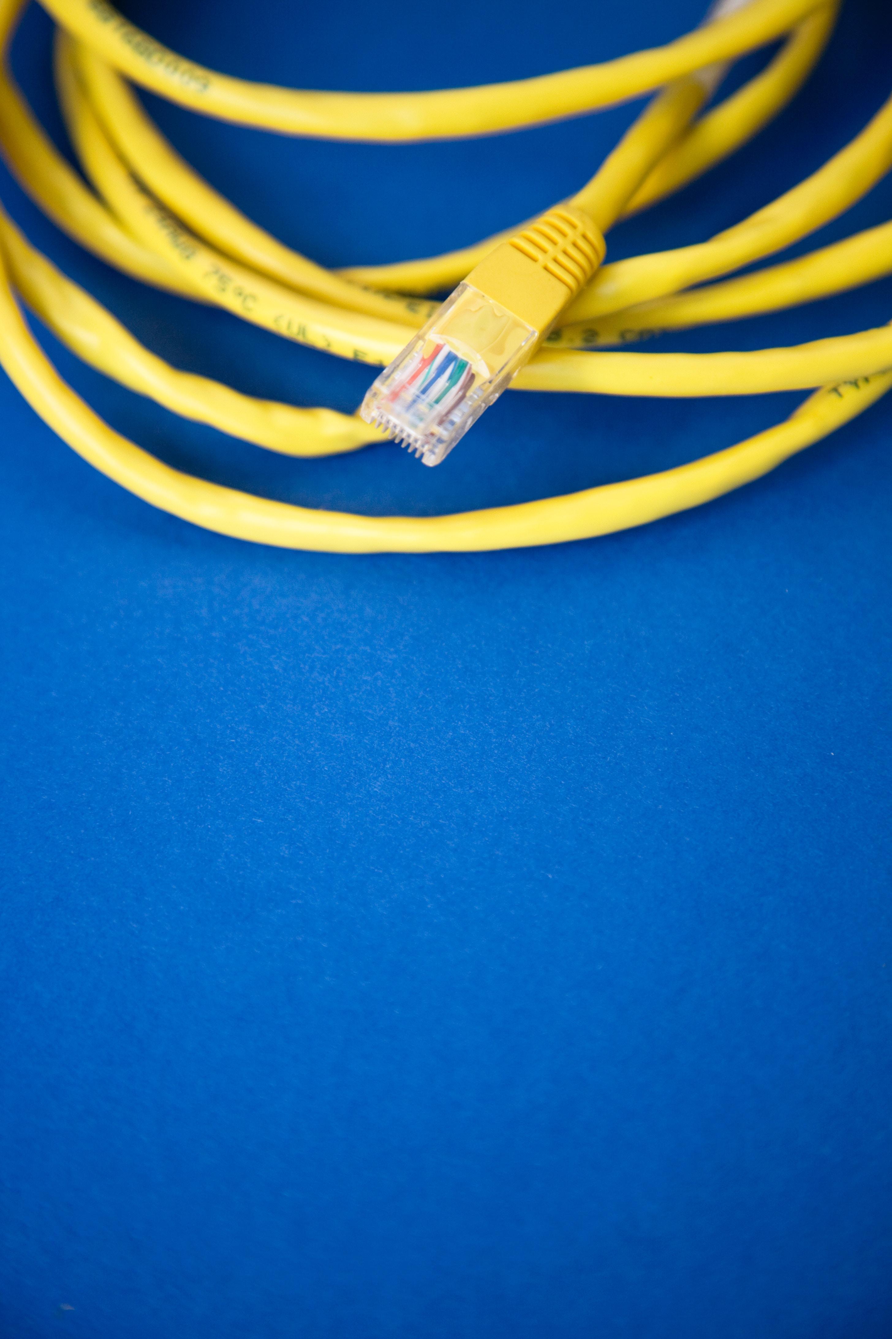
Twisted pair cables terminate with a plug that exposes the wires to whatever device they are interfacing with. The most common in computer networking is known as RJ45 (Registered Jack 45). Cables are plugged into Network Ports which are “generally directly attached to the devices that make up a computer network.”
Most network ports have two LEDs, an amber Link LED, and a green Activity LED. The link light will illuminate when a cable is connected properly, and the activity light will flash when data is passing over the cable. Port lights can sometimes assist in troubleshooting.
If you have a network port in the wall, it probably connects to a patch panel, which is a terminal for many cables, which are then run to a switch or router.
Ethernet and MAC Addresses
The most common protocol used to transmit data over network links is Ethernet. The datalink layer, using Ethernet, provides the means for software at higher levels (layers) to send and receive data. The datalink layer allows the higher layers to ignore the physical layer and function no matter what devices are connected. Your browser will function on WiFi or Ethernet without having to worry about it.
Ethernet came around in the 1980s, and has undergone some significant improvements but much of the protocol is essentially the same. In the old days, there were no hubs or switches, so networked computers were all on the same collision domain. Ethernet worked around this by using CSMA/CD (carrier-sense multiple access with collision detection). It is used to determine when the communication channels are clear, and when a device is free to transmit data. Basically, if the device “hears” that the wire is not being used it will send data. If there is a collision, both devices sense it and stop sending data for a “random” interval, which prevents the next collision.
Remember that a collision domain means that all nodes are receiving all traffic. Each node is given a unique identifier to be used in recognizing network traffic. This is called a MAC (media access control) address. A MAC address is a globally unique identifier attached to an individual network interface. It is a 48-bit number normally represented by six groupings of two hexadecimal numbers.
Hexadecimal: A way to represent numbers using 16 digits. This means a hexadecimal number can contain the numerals 0 through 9, and the letters A through F.
You can refer to each group of numbers in a MAC adress as an octet, which is, in computer networking, any number that can be represented by 8 bits.
The first three octets of a MAC address are the Organizationally Unique Identifier(OUI), which are assigned to individual hardware manufacturers by the IEEE. The last three octets are assigned by the manufacturer, but must be assigned only once, to keep each devices MAC address unique.
Ethernet uses MAC addresses to ensure that the data it sends has both an address for the machine that sent the transmission, as well as the one the transmission was intended for.
Unicast, Multicast, and Broadcast
When a device sends data to another device it is called unicast, and is always meant for one receiving address.
- If the least significant bit in the first octet of a destination address is set to ZERO, it means that Ethernet frame is intended for only the destination address.
- If the least significant bit in the first octet of a destination address is set to ONE, it means you’re dealing with a multicast frame. A multicast frame is sent to all devices on a local network. It may be accepted or discarded by the receiving devices based on criteria other than MAC address.
A broadcast is sent to every device on a network using a special destination called a broadcast address. The Ethernet broadcast address is all F’s, as in FF:FF:FF:FF:FF:FF. A broadcast is used so that devices can “learn more about each other.”
Dissecting an Ethernet Frame
Data Packet: An all-encompassing term that represents any single set of binary data being sent across a network. The term “data packet” does not refer to any specific layer or technology, it is just a concept. At the Ethernet level, data packets are known as Ethernet frames: a highly structured collection of information presented in a specific order. This means that network interfaces at the physical layer can convert bits coming over a link into data, or vice-versa.
The frame contains multiple mandatory parts:
- Preamble: 8 bytes (64 bits) long, and can be split into two sections. The first 7 bytes in the preambles are used to separate frames and also are used to set “clocks” to synchronize interfaces. The last byte is called the SFD (start frame delimiter) and signals that the preamble is over and that the actual contents will follow.
- Destination MAC Address: 6 bytes; The hardware address of the intended recipient.
- Source MAC address: 6 bytes;
- EtherType field: 16 bits; used to describe the protocol of the contents of the frame. (If there is a VLAN header it will precede the EtherType field. VLAN (virtual LAN) allows multiple logical networks on one physical network.)
- Payload: 0-1500 bytes; the actual data being transported.
- FCS (frame check sequence): 4-byte number that represents a checksum value for the entire frame. This checksum value is calculated by performing what’s known as a cyclical redundancy check (CRC) against the frame.
When a device is ready to send an Ethernet frame, it collects all this information, performs a CRC against this data, and attaches the resulting checksum value as the FCS at the end of the frame. The data is then sent across the link and the receiving computer performs a CRC against the received data. If the checksum is not confirmed, some data must be corrupted or missing, and a decision is made by higher protocols whether to ignore the frame or request that it is re-transmitted.
Quiz time. This was a long one.
No, wait…Three-quiz time.
Stay tuned for Course II, Week 2, The Network Layer.
Anker 20100mAh Portable Charger PowerCore 20100 – Ultra High Capacity Power Bank with 4.8A Output SoundPEATS Magnetic Wireless Earbuds Bluetooth Soylent Meal Replacement Drink, Original, 14 oz Bottles, Pack of 12
Source: https://t-tees.com
Category: WHAT