
Resistors in Series
Resistors are said to be in series whenever the current flows through the resistors sequentially. Consider Figure (PageIndex{2}), which shows three resistors in series with an applied voltage equal to (V_{ab}). Since there is only one path for the charges to flow through, the current is the same through each resistor. The equivalent resistance of a set of resistors in a series connection is equal to the algebraic sum of the individual resistances.
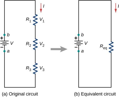
In Figure (PageIndex{2}), the current coming from the voltage source flows through each resistor, so the current through each resistor is the same. The current through the circuit depends on the voltage supplied by the voltage source and the resistance of the resistors. For each resistor, a potential drop occurs that is equal to the loss of electric potential energy as a current travels through each resistor. According to Ohm’s law, the potential drop (V) across a resistor when a current flows through it is calculated using the equation (V = IR), where (I) is the current in amps ((A)) and (R) is the resistance in ohms ((Omega)). Since energy is conserved, and the voltage is equal to the potential energy per charge, the sum of the voltage applied to the circuit by the source and the potential drops across the individual resistors around a loop should be equal to zero:
You are viewing: Which Circuit Has The Largest Equivalent Resistance
[sum_{i = 1}^N V_i = 0.]
Read more : Which Color Outlets Are Preferred For Vads
This equation is often referred to as Kirchhoff’s loop law, which we will look at in more detail later in this chapter. For Figure (PageIndex{2}), the sum of the potential drop of each resistor and the voltage supplied by the voltage source should equal zero:
[begin{align*} V – V_1 – V_2 – V_3 &= 0, [4pt] V &= V_1 + V_2 + V_3, [4pt] &= IR_1 + IR_2 + IR_3, end{align*}]
Solving for (I)
Read more : Which Epson Printer Can Be Converted To Dtf
[begin{align*} I &= frac{V}{R_1 + R_2 + R_3} [4pt] &= frac{V}{R_{S}}. end{align*}]
Since the current through each component is the same, the equality can be simplified to an equivalent resistance ((R_{S})), which is just the sum of the resistances of the individual resistors.
One result of components connected in a series circuit is that if something happens to one component, it affects all the other components. For example, if several lamps are connected in series and one bulb burns out, all the other lamps go dark.
Let’s briefly summarize the major features of resistors in series:
- Series resistances add together to get the equivalent resistance (Equation ref{equivalent resistance series}): [R_{S} = R_1 + R_2 + R_3 + . . . + R_{N-1} + R_N = sum_{i=1}^N R_i.]
- The same current flows through each resistor in series.
- Individual resistors in series do not get the total source voltage, but divide it. The total potential drop across a series configuration of resistors is equal to the sum of the potential drops across each resistor.
Source: https://t-tees.com
Category: WHICH