
When creating drawings for construction, the design intent is likely to change, meaning that designs will need to be amended. AutoCAD has many tools for modifying drawings.
Selecting Objects
AutoCAD has various methods for selecting individual or multiple objects. Each of the selection techniques can be used either before invoking a command or after.
You are viewing: How To Get White Glove To Move Screen In Autocad
Individual Selection
Hover the cursor over an individual object and left-click to select it. Clicking additional objects will add them to the current selection set.
Selection Windows
Selection Windows are rectangular areas specified in the drawing area with two clicks to determine the opposite corners of the window. The direction in which the window is drawn determines which selection method is used.
Left to Right – Window Selection
A Window Selection has a solid border and translucent blue fill. It selects all objects that are fully encompassed within the window. The two corners of the window must be specified from left to right.
Right to Left – Crossing Selection
A Crossing Selection has a dashed border and translucent green fill. It selects all objects that are intersected by the window or contained within it. The two corners of the window must be specified from right to left.
Fence
At any point when AutoCAD prompts for objects to be selected, type “F” and press [Enter] to invoke the Fence selection method. The Fence is a crossing line that will select all objects that it intersects.
Note: To remove objects from the current selection set, hold [SHIFT] and select them again.
Erase
The erase tool in AutoCAD removes objects from the drawing.
To erase an object, from the Ribbon Home tab > Modify panel, click the Erase button.
Command line: To start the Erase tool from the command line, type “E” and press [Enter].
Select the objects you wish to erase and press [Enter].
Move
Use the move tool to reposition objects in your drawing.
To move an object, from the Ribbon Home tab > Modify panel, click the Move button.
Command line: To start the Move tool from the command line, type “M” and press [Enter].
To move objects, select any objects you wish to move and press [Enter].
Two points need to be clicked, the move from point or base point and the move to point. Specify the base point and the second point will indicate how far the objects are to be moved and in what direction.
While moving, the objects will display in their original location and also attached to the cursor. On completion of the move, the originals will disappear leaving only the moved objects.
Copy
The copy tool works in much the same way as the move tool but creates duplicates of the objects.
To copy an object, from the Ribbon Home tab > Modify panel, click the Copy button.
Command line: To start the Copy tool from the command line, type “CO” and press [Enter].
Select the objects you wish to copy and press [Enter] to accept the selection.
Click the base point as the point to copy from.
Then specify the second point as the point to move to.
The command remains active with the current selection so that multiple copies can be created using the same base point.
Rotate
The rotate tool in AutoCAD rotates around a specified base point.
To rotate an object, from the Ribbon Home tab > Modify panel, click the Rotate button.
Command line: To start the Rotate tool from the command line, type “RO” and press [Enter].
Select the objects you wish to rotate and press [Enter] to accept the selection. Specify the base point around which you want to rotate them.
Type an angle to rotate the objects by or use the cursor to indicate an angle.
Note: The angle is always measured anti-clockwise from the East direction.
Array
The Array tool is used to copy objects in either a rectangular, polar or path fashion.
Original
Rectangular
Polar
Path
To use the Array tool, from the Ribbon Home tab > Modify panel, click the Array tool.
Command line: To start the Array tool from the command line, type “AR” and press [Enter].
Select the object or objects you wish to array, you will then be prompted Enter array type [Rectangular/PAth/POlar] <Rectangular>:
Rectangular
Click Rectangular from the drop down settings or type “R” in the command line and press [Enter].
The command line will prompt Specify opposite corner for number of items or [Base point/Angle/Count] <Count>, As you move your cursor, AutoCAD will preview the number of items being created.
Alternatively, press [Enter] to use the default option of Count. You will then be prompted to type in a number of Rows and Columns.
Once the number of items has been confirmed, you will be prompted Specify opposite corner to space items or [Spacing] <Spacing> move your cursor and the spacing will adjust.
Alternatively, press [Enter] to use the default option of Spacing. You will then be prompted for the distance between rows and the distance between columns. This distance is from one point on one shape, to the same point on the arrayed copy.
To complete the command, press [Enter].
Polar
Click Polar from the drop down settings or type “PO” in the command line and press [Enter].
You will then be prompted Specify center point of array or [Base point/Axis of rotation]. Click a point on the screen or type a coordinate to place the point about which the array will be created.
You will then be prompted Enter number of items or [Angle between/Expression] <4> type a number as required. The number includes the original shape e.g. type “6” will create 5 additional shapes.
Next you will be prompted Specify the angle to fill (+=ccw, -=cw) or [EXpression] <360> You can either click a point on the screen to indicate the angle or type a value.
Number of items: 8
Angle to fill: 180
Number of items: 8
Angle to fill: 360
Path
Click Path from the drop down settings or type “PA” in the command line and press [Enter].
The command line will prompt Select path curve, select an object as the path. Although you are prompted for a curve, this could be a Polyline, Line or Spline.
You will then be prompted Enter number of items along path or [Orientation/Expression] <Orientation> type a number as required. The number includes the original shape e.g. type “6” will create 5 additional shapes.
Finally you will be asked Specify the distance between items along path or [Divide/Total/Expression] <Divide evenly along path> Press [Enter] to use the default option to have even spacing along the path.
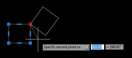
Grips
Most shapes created in AutoCAD can be modified using grip points. Select a shape to show the available grips. Click the grip you wish to edit. The grip changes from Blue to Red to indicate that it is “hot” and attaches to your cursor.
The hot grip is the presumed base point of any modifications unless a new base point is specified.
Using right click, you can access additional items such as relocating the Base Point. This allows you to modify the grip points from an unrelated or non-grip point on the screen.
Once you have selected Base Point, click a point on the screen such as snapping to another object.
Read more : How Did Donald Glover Getba Black Eye
Your Grip point will start to stretch out from the new base point, click a second point to identify the point to stretch to.
Hold [Shift] whilst manipulating a grip to restrict movement to the horizontal and vertical axis.
To edit more than one grip at a time, hold down shift as you select multiple grips. When you have selected all the required grips, release shift and select one of the grips again as the base point. This will now allow you to modify the geometry using all the selected grips and maintaining their relationship.
Using Grips to Add and Remove Vertices
With a grip selected, press [Ctrl] to cycle between Add Vertex, Remove Vertex and the default Stretch modes.
Add Vertex will create an additional vertex point after the selected grip. Press [Ctrl] until you see the plus sign on the cursor. Specify the point on screen where you wish to add a vertex.
Note: A vertex must be added after the selected grip. The direction in which the Polyline was created determines which initial grip needs to be selected. In the example below the Polyline was created in a clockwise direction.
Remove Vertex will delete the selected vertex point. Press [Ctrl] until you see the minus sign on the cursor. Pick on the screen to delete the vertex.
Using Basic Modify Tools with Grips
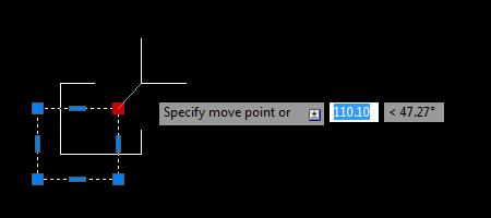
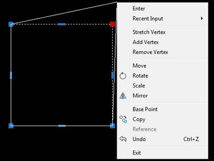
With a grip selected, right-click to access a number of the modify tools such as Move, Rotate, Scale, Mirror and Copy.
You can also press [Space] to cycle between Move, Rotate, Scale, Mirror, and the default Stretch modes.
Move invokes the Move command, using the hot grip as the default base point. Pick a point on screen to move the object to or specify a distance at the cursor prompt.
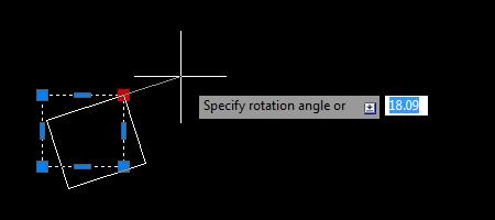
Rotate invokes the Rotate command using the hot grip as the default base point. Pick a point on screen to rotate the object or specify a rotation angle at the cursor prompt.
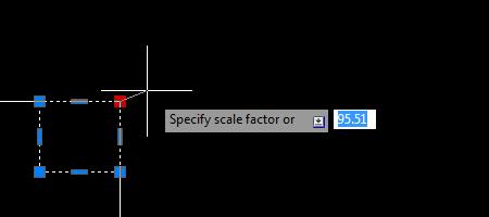
Scale invokes the Scale command using the hot grip as the default base point. Specify the scale factor at the cursor prompt.
Mirror invokes the Mirror command using the hot grip as the first point of the mirror line. Specify a point to determine the mirror line.
Use Grips to Lengthen a line
Hover over the grip of a Line object to reveal a shortcut menu with the default Stretch option and an additional Lengthen option. The Lenghten tool works very similarly to stretch but it locks the line to its current axis.
Click the Lengthen tool then specify a second point to
Note: With a grip of a line selected, press [Ctrl] to cycle between Stretch and Lengthen modes.
Quick Select
Quick select is used to select objects based on their properties. You may want to amend the properties of all Polylines in a drawing on a particular layer. Instead of selecting each entity separately, use the Quick Select feature.
From the Ribbon Home tab> Utilities panel, click the Quick Select button.
Command line: To start the Quick Select tool from the command line, type “QSELECT” and press [Enter].
The Quick Select dialog box will show.
Apply to Chooses to apply the Quick Select to either the Entire drawing or Current selection.If you haven’t selected any objects, click the button to the right of the Apply to drop-down, the dialog will hide, select your objects and hit return to show the Quick Select dialog box.
Object type selects the type of object you wish to find or set to Multiple to include all types of object. Only elements in your current drawing will be available.
Properties choose the property you wish to find such as Layer.
Operator
- = Equals will find objects that match the value you set in the Value drop-down.
- <> Not Equal will find all objects that don’t match the value you set in the dialog box.
- Select All will ignore any entry you add to the dialog box. This is useful if you want to find all entities of a specific type but aren’t worried about what properties they have.
Value sets the value of the property you wish to find.
How to apply specifies whether the new selection set includes or excludes objects that match the specified filtering criteria.
- Include in new selection set creates a new selection set composed only of objects that match the filtering criteria.
- Exclude from new selection set creates a new selection set composed only of objects that do not match the filtering criteria.
Append to current selection set specifies whether the selection by Quick Select replaces or is appended to the current selection set.
Source: https://t-tees.com
Category: HOW