1. Ford Transit 2020+
1.1. Overview
1.2. Behavior
The default behavior for all auxiliary switches is to be “powered at ignition only” (when key is in “run” position) in order to prevent a full discharge of the battery. Optionally, the behavior can be changed to “powered at all time” by the jumper fuse F15 relocation from position A to position B as shown below:
1.3. Gain Access
Here is how to gain access to the Auxiliary Fuse Panel (to relocate Jumper Fuse F15 if needed) and how to gain access the Auxiliary Switches Power Output (to wire your auxiliary loads):
You are viewing: What Are Upfitter Switches
1.3.1. Release the Glove Box Door
Press inward on the glove box (on both sides) to disengage the retaining tabs, then lower the door all the way. We weren’t able to make it work by hand, so we used a wrench to pry the sides:
You’ll then be able to lower the glove box door all the way down (notice the tabs in the photo below). At this point, you can also remove the cover located in the storage below the cup holder:
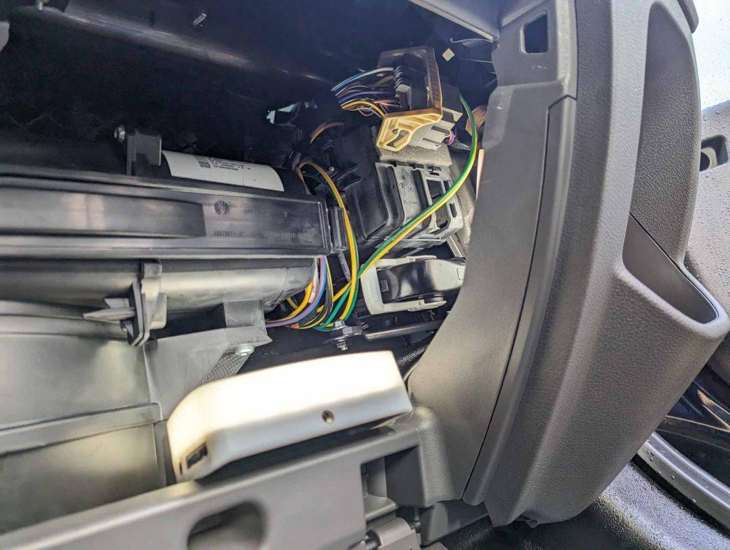
You can now see the Auxiliary Fuse Panel (A526) and the High Specification Vehicle Interface Connector:
1.3.2. Get proper lighting!
It’s dark in there. We got these LED lights; they’re small and you can fit them anywhere! We’re using them all the time in the van during our conversion:
1.3.3. Free the High Specification Vehicle Interface Connector
Pull back on the connector to free it from the Auxiliary Fuse Panel’s cover. It’ll make things easier a bit later. The High Specification Vehicle Interface Connector is used to connect loads to the AUX 1 (20A) and AUX 4 (20A), but we’ll come back to this a bit later:
1.3.4. Remove the Auxiliary Fuse Panel’s Cover
1.4. Wiring
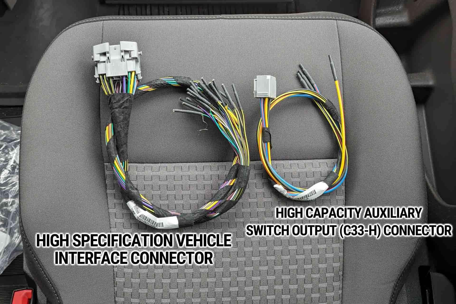
Now that we gained access to the connectors, we can wire our load(s) to the Auxiliary Upfitter Switches. You will need the following wiring harnesses; both are provided with your van (we found ours in the glove box compartment):
- 43-Pin High Specification Vehicle Interface Harness (P/N: KTHK4V14A11BB): AUX 1 and AUX4.
- 6-Pin High Capacity Auxiliary Switch Output Harness C33-H (P/N: HK4V14A411JA): AUX 2 and AUX 3.
Can’t find your harnesses? You can buy them from your local Ford dealer (see part numbers above) or Buy on eBay.

1.4.1. AUX 1 and AUX 4 Wiring
Read more : What Is A Loafing Shed
AUX 1 and AUX 4 upfitter switches are wired via the High Specification Vehicle Interface (43-Pin Connector). First things first, the interface (in the glove box) comes from factory with a “blank” cover. Remove it:
At this point we could simply connect the provided harness, then connect our load to AUX 1 (yellow wire) and/or AUX 4 (green/brown wire). But we would have a bunch of unused wires hanging around, that harness is quite bulky. That could work, but we’ll go for the clean install and transfer the YELLOW and GREEN/BROWN wire to the “blank” connector we removed in the previous step. This way we only have the wires we need:
And into the van it goes:
1.4.2. AUX 2 and AUX 3 Wiring
AUX 2 and AUX 3 upfitter switches are wired via the High Capacity Auxiliary Switch Output Harness (C33-H, 6-Pin Connector). First things first, the interface (in the glove box) comes from factory with a “blank” cover. Remove it:
The C33-H harness doesn’t have to be modified, we simply connected it to the van as-is:
1.4.3. Job Closeout
We won’t be connecting loads to our auxiliary upfitter switches at the moment, so we reinstalled the connectors and the auxiliary fuse panel cover back until we’re ready to wire them. See you next time!

Ford Transit 2015-2019
Each switch is ignition supplied (they only work when the key is in “run” position) and can provide a 12V/20A max output to an auxiliary load (such as an Air Lift Spring Kit Compressor, Exterior LED Bar, etc.).
To wire auxiliary loads to the switches, you will have to order the Motorcraft Upfitter Switch Wiring Pigtail C33-H (Part Number WPT-1408). It is NOT provided with the van! Without it, you don’t have access to the output of the switches:
Now, let’s get the driver seat out of the way because this is where we access the switches output. There are four screws to remove; two in the back of the seat:
and two screws in the front of the seat:
Read more : What Is Daddy Ball
Don’t take the seat off yet! We still have to detach the electrical harness:
We’re now going to take the batteries cover off. We have the dual batteries option; your setup might be different!
Remove those two screws to free the metal plate:
Here is the C33-H connector! We will connect our WPT-1408 pigtail to it.
While we’re here, if you ever blow one of the Upfitter Auxiliary Switch 20A fuse, this is where to replace it (see Fuse Panel in the picture above).
The WPT-1408 Wiring Pigtail kit comes with four crimp splices and shrink tubes, but we decided to install female quick-release terminal instead. This way, we can easily add or change the loads in the future:
We can now connect the WPT-1408 Wiring Pigtail Kit into the C33-H connector:
Now turn the ignition on and flip those switches up!
(you can use a multimeter to find out what switch power what wire…)
You might be interested in…
(We’re using the upfitter auxiliary switch #1 to power our Air Lift Spring Kit):
Source: https://t-tees.com
Category: WHAT
