Up to Standards
- Author: Mike Weinberg, Contributing Editor
One of the least-understood and most-commonly misdiagnosed complaints/problems with manually shifted transmissions and transfer cases is synchronization.
In a manual transmission or transaxle, a number of shafts and speed gears are moving at different speeds because of the number of ratios in the gearbox. To change gears without gear clash, the transmission has a number of synchronizer assemblies that engage the desired speed gear at the direction of the driver.
You are viewing: Which Part Of A Synchronizer Is Splined To A Shaft
The speed gears are in constant mesh with opposing gears that determine the ratio for each speed the driver can select. The speed gears freewheel on the shafts they are mounted on, and the synchronizer assemblies are splined to the shafts on which they are mounted. Since synchronize means to make several things happen at the same time, the design is made to get the speed gear being selected to move at the same speed as the shaft and synchronizer assembly. When the shaft speeds are equal it is possible to engage the sliding sleeve of the synchronizer assembly to the speed gear being selected without grinding or clashing. This process must work during both upshifts and downshifts and coordinate the different shaft speeds with a precise timing under differing throttle openings.
Many conditions affect the operation of the synchronizers and can create shift problems. Many of these conditions are external to the transmission. To diagnose and repair a manual transmission properly, the technician must understand both the theory of operations and how the parts relate to each other to produce a good, smooth-shifting end product for the customer.
Understanding the theory:
Although there are many different designs of synchronizers, all of them function in the same way. The synchronizer assembly consists of a hub with internal splines that bind it to the shaft on which it rides. The hub has a set of external splines that mate with splines inside the sliding sleeve, which can move back and forth on the hub. At either end of the sliding sleeve are matched sets of engagement teeth that engage the speed gear. Each sliding sleeve can mate with two speed gears: 1st and 2nd gears, 3rd and 4th gears, and 5th and 6th gears, and one for reverse gear in many late-model transmissions.
The synchronizer assembly also has slots machined in the hub for keys (struts, dogs, pressure pieces etc.) that move in the same direction as the sliding sleeve. These keys engage slots milled into the synchronizer or blocking ring, which rides on a machined cone that is part of the speed gear. Behind the cone of the speed gear is a machined set of engagement teeth that mate with the engagement teeth on either end of the slider. The synchronizer ring also has a set of engagement teeth that match those on the sliding sleeve and the speed gear.
The mechanics of a synchronized shift are relatively simple. The driver selects a gear to be engaged using the shift lever, which in turn moves a shift fork connected to the synchronizer sliding sleeve. As the sleeve moves toward the speed gear, the keys move the synchronizer ring into contact with the cone of the speed gear. The synchronizer ring is a wet clutch that provides friction to the cone of the speed gear to slow or accelerate the speed gear to match the speed of the shaft on which the synchronizer assembly is riding.
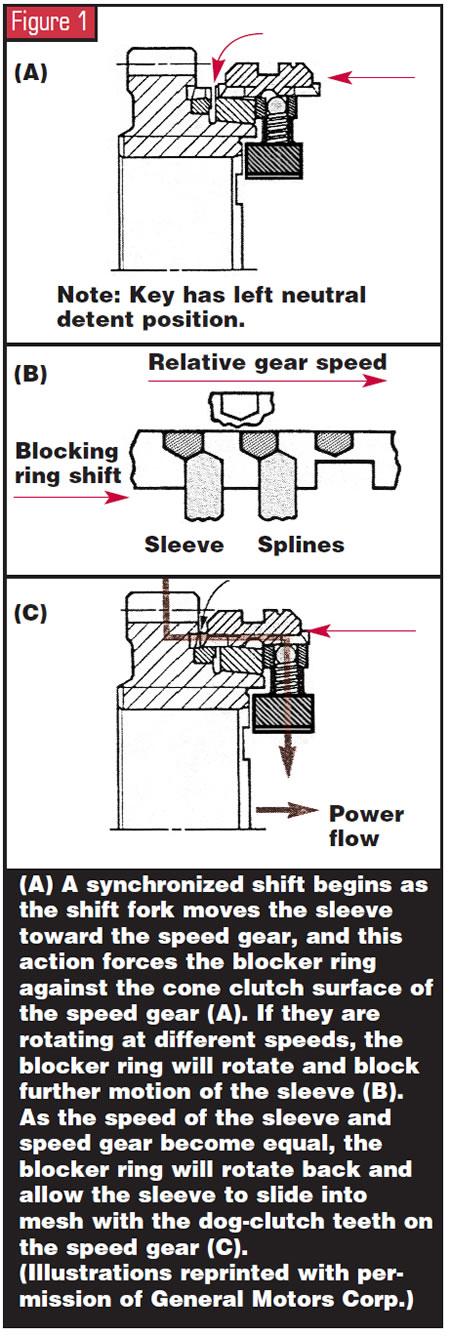
At this point the synchronizer ring will not let the sliding sleeve engage the teeth on the speed gear until the shaft speed and gear speed match (synchronize). When the shaft speed equalizes with that of the speed gear, the friction on the blocking or synchronizer ring relaxes and the ring’s external teeth line up with the sliding sleeve and permit it to travel to fully engage the teeth of the speed gear, completing the shift quietly. It’s obvious that if any of these components are worn or damaged this timing process will not work and gear grind occurs.
Read more : Which Of The Following Foods Does Not Contain Cholesterol
As part of this discussion of theory it is now time to understand the relationship of gear ratio and shaft speeds to the shift process. Using a 1st-to-2nd shift for this example and to make the math easy, assume that the ratio of 1st gear is 2-1 and the ratio for 2nd gear is 1.5-1. The driver accelerates to 4,000 rpm and begins the shift. At this moment the main shaft is traveling at 2,000 rpm (4,000 divided by 2 = 2,000) and the drive wheels are driving the main shaft. At this point the 2nd speed gear is rotating at 2,667 rpm (4,000 divided by 1.5.) The speed of the clutch disc has to drop to 3,000 rpm for 2nd gear to reach the same speed as the main shaft and synchronizer assembly (3,000 divided by 1.5 = 2,000). At this point the shift can be completed with no clash.

Here you can begin to realize external conditions that can create problems with the shift, where a poor clutch release or a driver hurrying the shift can affect the outcome by altering the timing of the shift event. An improperly adjusted or damaged clutch that will not properly disconnect the power flow from the engine to the input shaft of the transmission will quickly damage the friction capability of the synchronizer rings and, in short order, cause permanent damage to the synchronizers and gear train.
Synchronizer-ring design:
A synchronizer or blocking ring works as a friction device much the same as brakes and clutches. These components, through friction and pressure, turn motion (kinetic energy) into heat and slow or accelerate a moving shaft.
Older designs of synchronizer rings are either brass or bronze and have sharp threads running around the inside diameter of the ring, with a series of grooves running across the threads perpendicularly. The sharp threads are designed to cut through the oil film on the cone of the speed gear, and the slots help to exhaust the lube through centrifugal force, ensuring that the ring can grab the speed gear instead of skidding on a film of oil.
Later designs use linings made of paper (similar to automatic clutches), carbon fiber and various sintered-metal alloys. All these materials provide better holding power than brass or bronze. An important note here is that all these designs are made to work with a specified transmission lubricant. The 90-weight gear oil used in the past is almost extinct and should never be used with later-design ring linings.
In the first place, the later-design linings are porous and absorb lubricant, and once they absorb 90-weight they will never fully purge themselves of the high-viscosity fluid. It stands to reason that the thicker the fluid, the higher the drag on the gear train running through it. High-viscosity fluids create cold-shift problems and add parasitic drag to the components, robbing fuel mileage.
Another external source of shift problems is the use of an incorrect lubricant. The high content of sulfur compounds in gear oils attacks the ring linings, and the viscosity prevents the rings from exhausting the fluid, creating gear clash. Most late-model transmissions are specified to run on ATF or specially formulated 5W-30 motor oils with special additive packages to provide the proper coefficient of friction for smooth synchronizer function. It is surprising how many shops, in their need to get a job out the door, will put any kind of lube in the transmission without regard to the shift consequences. The correct lube is as important a part as any bearing, seal or gear you will install. An incorrect lube may force you to disassemble the transmission you just rebuilt and replace the new synchro rings you just installed.
Design issue with synchronizer rings:
With the older-design brass or bronze rings, the service manuals would list a specification for measuring synchronizer-ring reserve, which was measuring by placing the ring on the cone of the speed gear and using a feeler gauge to measure the ride height of the ring from the synchronizer teeth on the speed gear. The problem with this is that there was no way to measure the integrity of the cone on the speed gear. The cone is tapered and impossible for the average shop to measure even if it had the proper specs from a print.
Read more : Which Statement Best Describes How The Fed Responds To Recessions
The correct and simple way to measure the quality of the taper on the speed gear is with machinist layout bluing or a good permanent felt marker. Clean and degrease all the cones on the speed gears and coat the cones with layout dye or felt marker. Then place a new ring on the cone and twist it on with force. Remove the ring and look at the pattern it made on the cone. It should be a constant mark around the cone from the top to the bottom of the ring. If there are skips or just a thin band around the gear cone at the top or bottom, the speed gear needs to be replaced. This is something that needs to be done during the teardown and rebuild process before you quote a price. Anything you do not set a price on will become your problem once the customer has agreed to a “final” price.
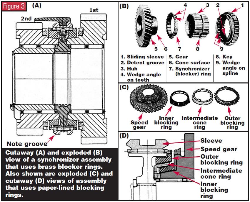
Newer ring designs have double- and triple-cone synchronizer rings. Having friction surfaces on both the inside and outside of the ring doubles or triples the surface area available for working the ring without increasing the diameters of the gears and synchronizers. This type of setup is common today, and measuring the synchronizer reserve with a feeler gauge is almost impossible. The only way to ensure that you have complete working coverage of the cones is to use the dye or felt-marker method. Many of the sintered-alloy type of linings on late-model rings have an aggressive coefficient of friction and will wear out the speed-gear cones.
Diagnosis and separating synchronizer-ring problems from other causes:
This is where the most confusion begins in diagnosing shift problems. Synchronizer rings can cause grinding and gear clash. They also can cause shift “block-out,” where a shift cannot be completed and is literally blocked from further movement of the shift lever. The ring will never create gear jump-out and in many instances will not be the cause of notchy, dragging shifts. To quickly eliminate external causes with shift problems, you need to make a series of checks of the driveline components. Is the unit filled with the correct oil? Is the lube in good condition or burnt beyond recognition? Is the clutch properly adjusted for a full release, and are the hydraulics or release linkage functioning properly?
A quick, easy test of the clutch setup is to jack the vehicle to get the drive wheels off the floor or put the vehicle on a lift with all four wheels off the ground. Now start the engine and go through all the gears with the drive wheels spinning freely. If the transmission now shifts better with little or no gear clash, the problem is related to clutch release. This, however, does not mean that the customer has not done internal damage to the unit by driving with a bad release for an unknown amount of time. Also important to note is that a poor clutch release will not always show up in all gears. Many 3-4 shift problems are clutch related, but the technician falsely believes a bad clutch will show up in all gears.
Another clue about clutch problems is sheared synchronizer keys, usually on the 3-4 synchronizer. The keys shear into pieces because the clutch did not disconnect the input shaft from the engine. This can be caused by the clutch not releasing as desired or by a driver who is either rushing a shift or “power shifting” without the clutch or not getting off the throttle when making a shift.
Gear jump-out is defined as the shift lever placing the transmission in the desired gear and then having the unit jump out of gear immediately when the clutch is engaged or when a change in throttle position occurs while driving. The synchronizer ring has NOTHING to do with gear jump-out. The causes are excess end play within the unit allowing the shafts to move the slider off the speed gear, worn or damaged shift forks or shift linkage, worn or damaged back taper on the speed gear or sliding sleeve, worn or damaged powertrain mounts, bent or out-of-balance driveshafts, or misadjusted shifters or cables.
Notchy, grinding shifts or blocked-out shifts are the result of worn synchro rings, damaged engagement teeth on the slider or speed gear, excess end play on a gear or shaft, worn or misadjusted shift linkage or forks, bad clutch release, driver shifting at too high an engine speed for the transmission components, or trying to rush the shifts or failing to use the clutch.
Understanding the components and their relationship to synchronized shifts should help you to make faster, more-accurate diagnostic decisions. Paying attention to details during teardown and rebuild will help reduce comebacks and make the work more profitable. Using the right lube for the unit will ensure your customer’s satisfaction and, it’s hoped, repeat business. Word-of-mouth recommendations are the best advertising.
Source: https://t-tees.com
Category: WHICH